Description
* When inquiring, please provide your LD current and voltage (required). The current and voltage of TEC (if any, please provide), we will tailor it for you according to the current and voltage of the pro.
.


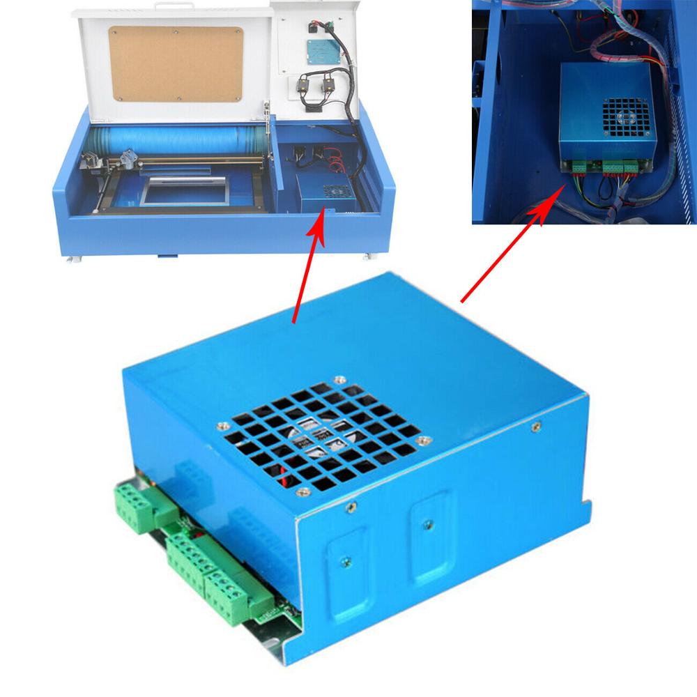
Circuit board description
One. Terminal definition:
1. + 5V, positive and negative of GND input voltage
2.LD-, LD + Connect the positive and negative pole of LD
3.CL +, CL-: Connect the positive and negative poles of TEC
4. RT +, RT1- connect the two poles of the thermistor
5. SIG-, SIG + plus external signal positive and negative
2. S2 position switch is a mode selection switch, dial to T + (up) is TT + mode, dial to T- (medium) TT- mode, dial to A (down) ANALOG mode;
three. S1 is the display selection switch, LD current, TEC temperature (resistance); dial I (upper) to display the current, R (medium) to display the temperature;
1. I-current display such as 0.5V is 5A
2. R-Temperature Display The multimeter voltage range as measured -0.1V means 10K thermistor resistance
four. Potentiometer
W5 potentiometer is a temperature regulator, adjust it to change the output size of TEC.
W2 potentiometer is LD current regulator, adjust it to change the output size of LD;
W3 and W4 LD current limit. 5A now
Current limiting method: If you want to limit to 3A, choose W2 modulation maximum, then adjust W4 to 3.1A, and then adjust W3 to 3A