Description
Latumab Driver Board for LP171WP4 TLB1 / LP171WP4 TLB2 / LP171WP4 TLB3 / LP171WP4 TLB4 / LP171WP4 TLB5 LVDS 17″ Screen Display Matrix TV + HDMI + VGA + USB 1440×900 Controller Board
- Brand Name: latumab
- Product Type: Tablet LCD
- Display Size: >13 Inch
- Model Number: LP171WP4
- Screen Type: Eletromagnetic
- Compatible Brand: Universal
- Compatible with 1: LP171WP4-TLB1
- Compatible with 2: LP171WP4-TLB2
- Compatible with 3: LP171WP4-TLB3
- Compatible with 4: LP171WP4-TLB4
- Compatible with 5: LP171WP4-TLB5
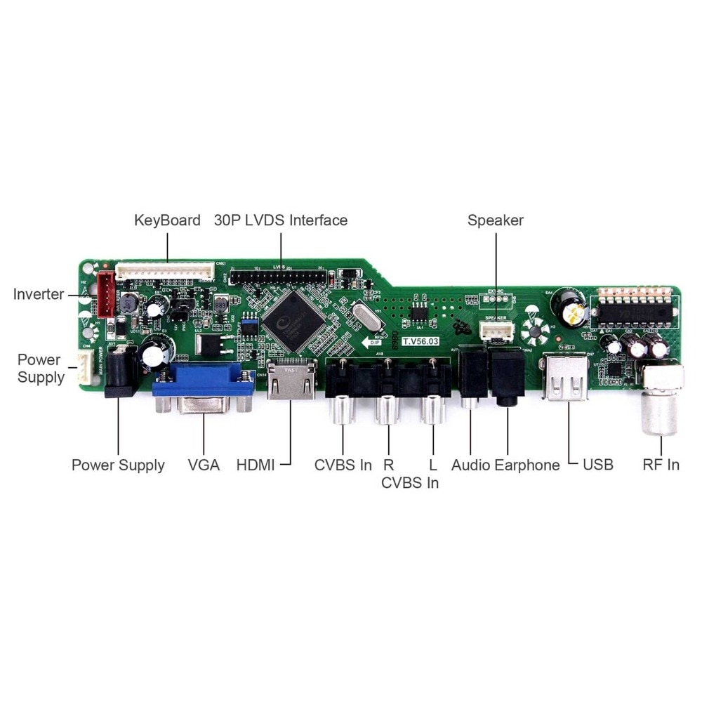
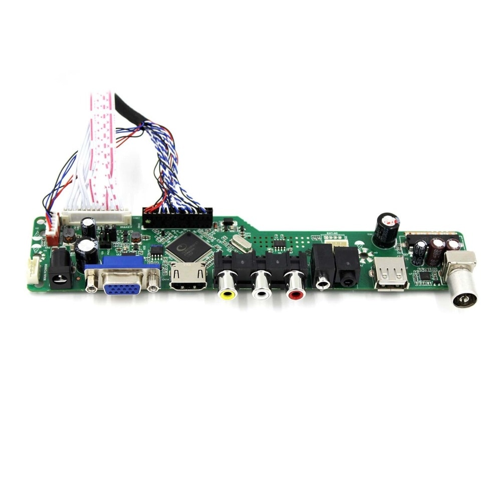
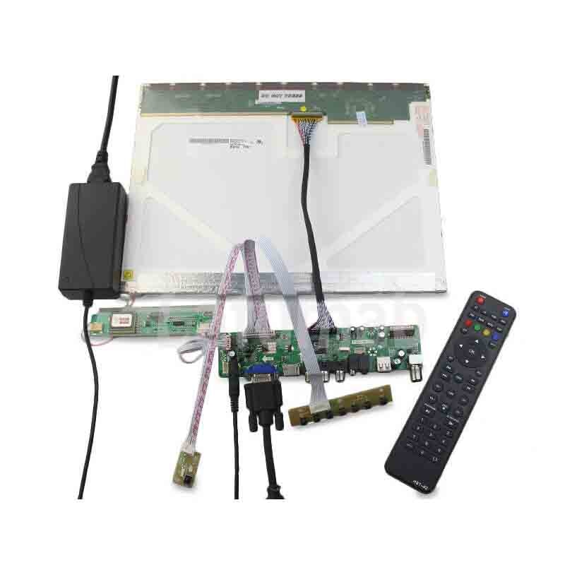
LCD Controller Board:
HDMI VGA AV USB RF LCD Board Work for LVDS Interface LCD Screen
Input Power Adapter: 12V/3A~12V/4A.
Come In Standby Model When Not Input Signal
USB Support Video
AV Compatible With PAL And NTSC
Video Input: HDMI VGA AV USB RF
Audio Input: HDMI PC-Audio
Audio Output: Speaker Connector
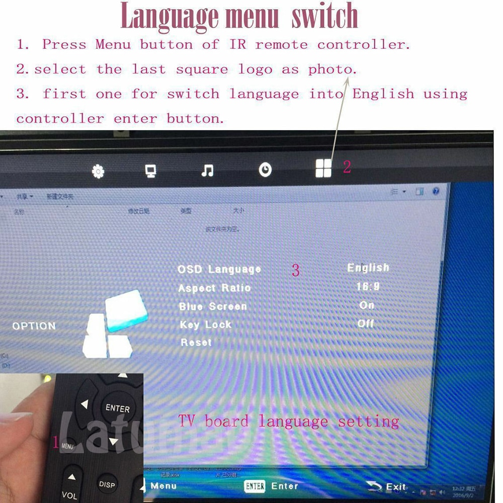
OSD: Brightness Contrast Auto Language And So On
Language: English French German Spanish And So On
Board Size:188mm x 43mm x 17mm
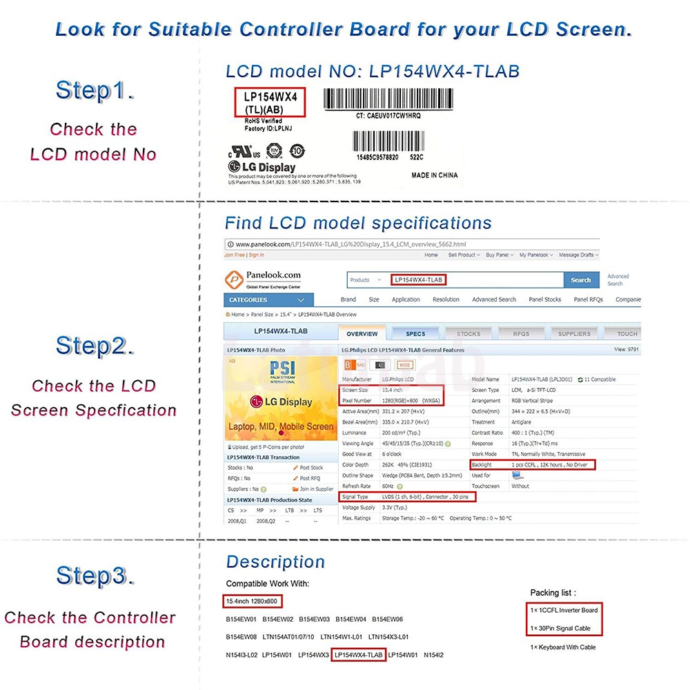
Compatible with:
LP171WP4-TLB1
LP171WP4-TLB2
LP171WP4-TLB3
LP171WP4-TLB4
LP171WP4-TLB5
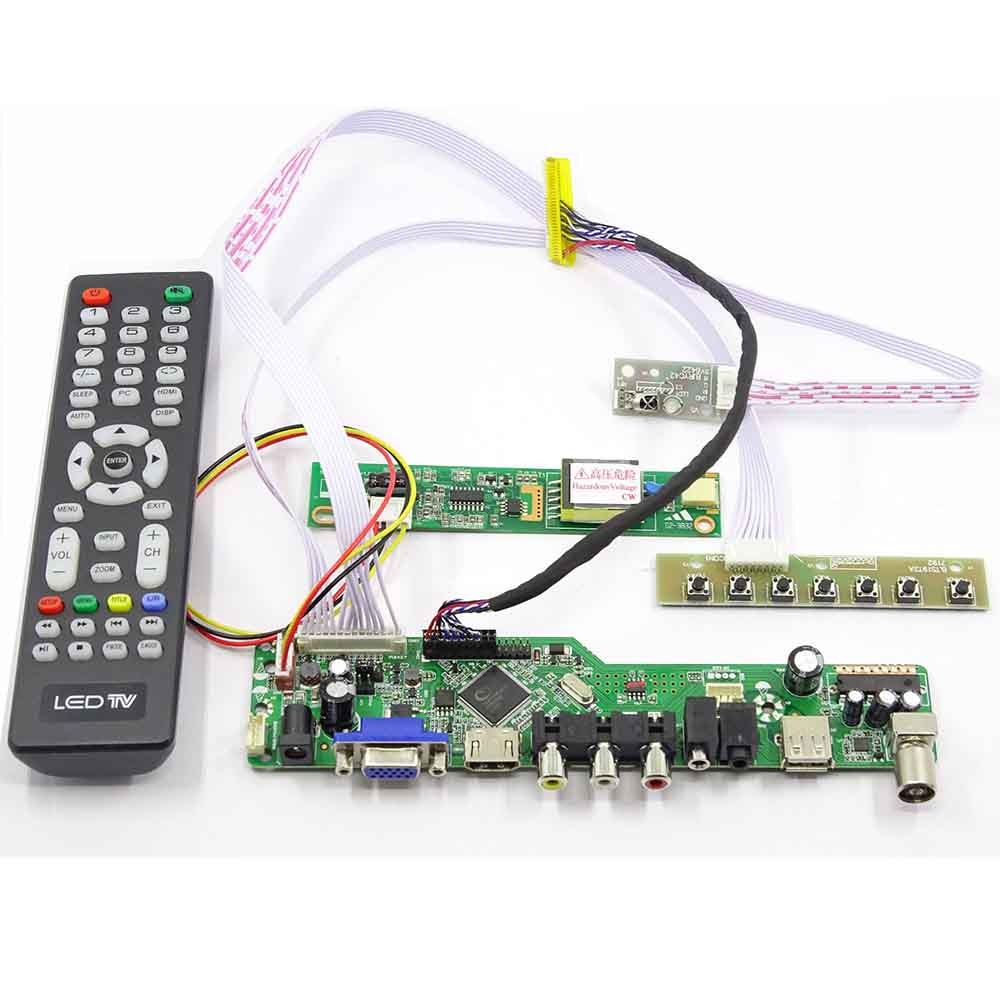
Packing list:
1× LCD Controller Board
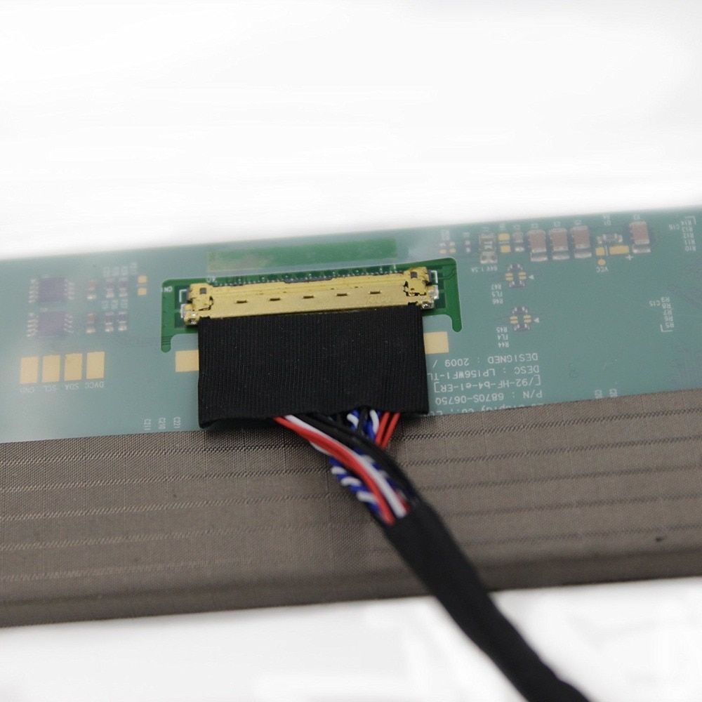
1× LVDS Signal Cable
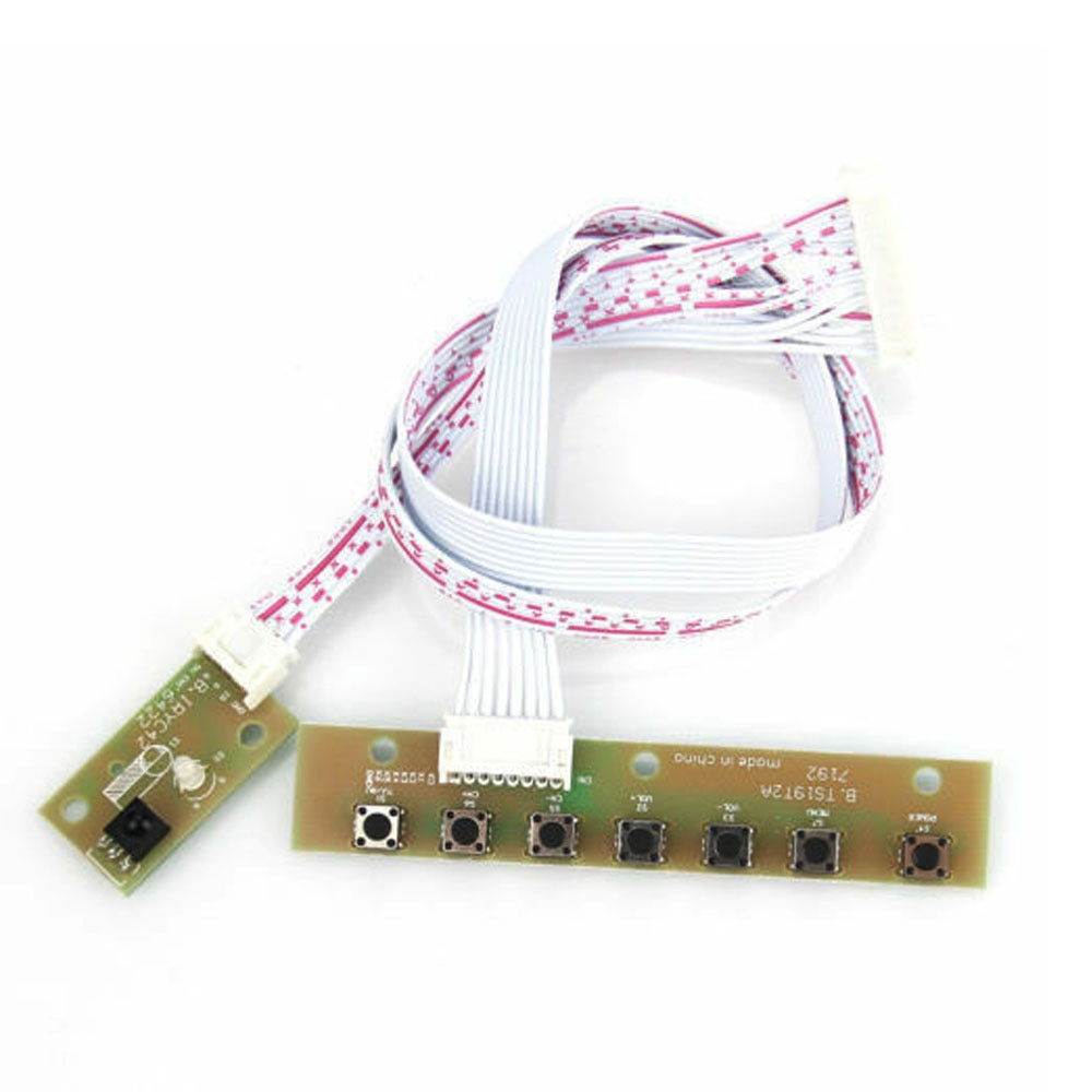
1× Keyboard With Cable
1× Inverter Board
1× Remote Control (Battery Not included)
Please note:
* If you not ensure model, please do not hesitate contact us directly.
* The adapter power need 12V 3A, not included; If you need buy the adapter power, please contact us.
* Pictures are only reference. We will match the corresponding board according to the ordered model.
FQA:
Q1: LCD screen shows a black screen after power on.
–A1: 1. Please confirm whether the screen backlight cable is connected to the booster board(inverter board). If not, connect it and power again.
2. Do some exchange test: Change the input signal to test; Change power adapter to test; Change the signal source to test; Change the signal cable to test; Change the LCD screen to test. And so on.
Q2:The signal cable can’t connect to the screen connector.
–A2: If your screen is eDP connector screen, but you bought the board which fit for the LVDS connector screen. For example, if your screen LP156WX4-TP(X)(X), but you get a controller board that fits for the LVDS controller board, such as LP154WX4-TL(X)(X), It will not match your screen. Then please choose the return reason “get the wrong product”. Or contact the seller first.
Q3: LCD screen image is not displayed correctly or show a white screen. Or the LED of the keypad flashes red and green alternately.
–A3:1. Make sure that the signal cable which connects to the LCD screen connector with the right direction. (Pin1 to Pin1, some panel the cable connector can be assembled by two direction, so sometimes when change it to back direction, it will work well)
2. Please confirm whether the resolution of the LCD screen is the same as the resolution of the LCD controller board (Please refer to the controller board purchase link which has marked compatible resolution, use the screen type to search on the network to confirm its support resolution), if not, please contact with seller, some boards after updating the firmware will fix this problem.
Q4: The LCD screen has images but is very dark. (Use a light torch to check if inside the screen have an image or not)
–A4: Please confirm whether the screen backlight cable is connected to the inverter board (booster board). If the connecting condition is OK, maybe the inverter board broken, if catch this problem, please contact us, we can send you a replacement.
Q5: The display keeps restarting after power on.
–A5: The input current of the power adapter is too small, please change the adapter with larger output current (2A or greater than 2A)
Q6: Power on, after a few seconds, the display goes black screen.
–A6: If you do not connect the signal cable (no input source), it will enter the standby mode after a few seconds of power. Please connect the input signal when you power on and use the keypad to switch to the appropriate channel.
Q7 : When not connect the signal cable to the LCD, power on the board, the keyboard LED is red or green. And then when you connect the cable to the LCD screen, the keyboard LED is off.
–A7: This is due to the definition of the signal cable is incorrect, please contact the seller to confirm if the seller has a compatible LCD screen signal cable or not.
Q8.: The computer detects that the driver board is connected but the LCD screen is not displayed.
–A8: If HDMI or DVI signal is connected. Please set on the computer to ensure that the HDMI DVI output is available.
Q9: Resolution is not supported.
–A9:1. Please change to other resolutions to confirm if they can display normally or not.
2. The input resolution is inconsistent with the LCD menu display resolution, it is due to the LCD screen controller board writes the common resolution, corresponding to the special resolution, and the control board menu displays the common resolution. If you want to display the same resolution, it needs to modify the EDID data of the LCD screen. If you encounter this situation and need to improve it, please contact us.
Q10: The screen shows several colors picture changing when you just power the board or the screen Color shows a factory mode OSD when you power on and input signal to the board.
–A10: This is factory mode, please help to use the keyboard ON/OFF key to turn off the board, then turn on, it will automatically exit the factory mode, and will work as normal.
Q11: The LCD screen original cable can’t be connected to the controller board.
–A11: Please remove the original signal cable that comes with the LCD screen, and use the cable which we provided with the controller board.
Q12: For the Type-C board, after the Type-C is connected, there is no signal on the LCD screen.
–A12: Please confirm the purchase link. If one Type-C is used to supply power and the other is used to as signal input, both Type-C needs to be connected.
Q13: When to use Type-C connect to the Phone, it can’t turn on or the brightness is very low.
–A13: 1. The input current of the mobile phone is not enough, and it is not possible to input enough current to allow the control board to run while transmitting signals.
2. When the phone is turned on, the default brightness is turned on. The input current of the mobile phone is not enough. You need to connect an additional power adapter to the control board.
Q14: The main chip is hot.
–A14: The temperature of the new board chip is less than 70 degrees Celsius (150 degrees Fahrenheit) at room temperature. If you are worried about heat dissipation, you can add a heat sink.