Description
- Brand Name: Eiechip
- Origin: CN(Origin)
- Condition: New
- Type: Voltage Regulator
- Model Number: L298N Driver module
- Application: Computer
- Operating Temperature: standard
- Supply Voltage: 5V
- Dissipation Power: standard
- Package: SMD
- L298N: L298N Motor Drive Board Module
- L298N 1: L298N DC stepper motor
- L298N 2: L298N Robot Smart Car
- L298N 3: L298N for Arduino
- L298N 4: L298 driver board module
| The following is Top Selling products buy navigation Recommend – Best Match |
| Follow the store to get fan coupons and exclusive fan discounts! You can click here |
|
|
|
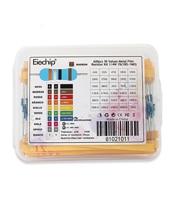
Electrolytic Capacitor |
||
|
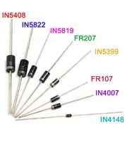
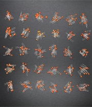
100pcs 1N4148-1N5408Rectifier Diode set |
|
|
|
|
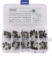
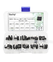 50pcs Transistor 10Values LM317T-L7824
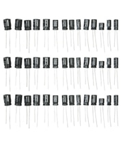
| New Arrivals |
| Follow the store to get fan coupons and exclusive fan discounts! You can click here |
|
|
|
|
|
|
|
|
|
|
|
|
Dear friend, please read the baby description carefully before buying the product.
Module name: Double H-bridge motor drive module
Working mode: H bridge drive (dual channel)
Main control chip: L298N
Logic voltage: 5V
Driving voltage: 5V-35V
Logic current: 0mA-36mA
Drive current: 2A (MAX single bridge)
Storage temperature: -20℃ to +135℃
Maximum power: 25W
Size: 43*43*27mm
The L298 chip is a brand new genuine chip. The SMD aluminum electrolysis uses two 35V 220UF high voltage and high capacity capacitors, while the imitation module uses a refurbished 2 hand chip, 35V 100UF and 10V 100UF low voltage and low capacity capacitors.
Features:
★ This module uses ST’s L298N as the main driving chip, which has the characteristics of strong driving ability, low heat generation and strong anti-interference ability.
★ This module can use the built-in 78M05 to get power through the drive power supply part, but in order to avoid damage to the voltage regulator chip, when using a drive voltage greater than 12V, please use an external 5V logic power supply.
Precautions:
1. When your drive voltage (marked as 12V input in the above figure, the actual acceptable input range is 7-12V) is 7V-12V, you can enable the onboard 5V logic power supply, when using the onboard 5V power supply , +5V in the interface
Do not input voltage for power supply, but you can draw 5V voltage for external use. (This is a regular application!)
2. When the driving voltage is higher than 12V, less than or equal to 24V (the chip manual suggests that it can support up to 35V, but according to the
It is very remarkable that 298 conservative application of maximum voltage support up to 24V has been verified! ), for example, to drive the rated voltage to
18V motor. First, you must remove the jumper cap of the onboard 5V output enable. Then connect 5V outside the 5V output port
5V enable is a control signal with a level of 5V. When this signal input is valid and the power supply in the motor drive module is normal, the motor drive module outputs current. Otherwise, even if the power supply is normal, there is no current on the motor.
The voltage supplies power to the internal logic circuit of L298N. (This is an unconventional application of high-voltage drive!)

Product parameters:
1. Driver chip: L298N dual H-bridge DC motor driver chip
2. The power supply range Vs of the drive part terminals: +5V~+35V; if the board needs to be powered, the power supply range Vs: +7V~+35V
3. Driving part peak current Io: 2A
4. Logic part terminal power supply range Vss: +5V~+7V (can take electricity in the board +5V)
5. Working current range of logic part: 0~36mA
6. Control signal input voltage range:
Low level: -0.3V≤Vin≤1.5V
High level: 2.3V≤Vin≤Vss
7. Enable signal input voltage range:
Low level: -0.3≤Vin≤1.5V (control signal is invalid)
High level: 2.3V≤Vin≤Vss (control signal is valid)
8. Maximum power consumption: 20W (when temperature T=75℃)
9. Storage temperature: -25℃~+130℃
10. Drive board size: 48mm*43mm*33mm (with fixed copper pillar and heat sink height)
11. Drive board weight: 33g
12. Other extensions: control direction indicator light, logic part of the electrical interface.
Instructions for use:
Stepper motor drive: ENA and ENB on the board are effective when the level is high, the level here refers to the TTL level. ENA is the enable terminal for A1 and A2, and ENB is the enable terminal for B1 and IB2. BJ is connected to the common end of the stepper motor.
The control logic of the stepper motor is as follows, where A, B, C, and D are the four coils of the stepper motor. A 1 indicates that there is current passing, and a 0 indicates that no current flows. The coil connection diagram is shown in the following figure (taking a four-phase stepper motor as an example)

L298n motor drive board around the robot
product manual:
This L298N driver module uses ST’s L298N chip, which can directly drive two 3-30V DC motors, and provides a 5V output interface, which can supply power to the 5V single-chip circuit system, supports 3.3VMCU control, and can easily control the speed of the DC motor. And direction, can also control 2-phase stepper motor, is a must for smart car.
Product parameters:
1. Driver chip: L298N dual H-bridge driver chip
2. The power supply range VMS of the driving part terminals: +5V~+35V
3. Drive part of the peak current Io: 2A/bridge
4. Logic part terminal power supply range Vss: 4.5-5.5V
5. Working current range of logic part: 0~36mA
6. Control signal input voltage range: high level 4.5-5.5V low level 0V
7. Maximum power consumption: 20W
8. Storage temperature: -25℃~+130℃
9. Drive board size: 55mm*60mm*30mm
10. Drive board weight: 33g
11. Other functions: control direction indicator light, power indication, current detection, and electrical interface in the logic part.

Product introduction: The motor drive module is very suitable for use in battery-powered smart cars, toy cars, robots, etc. The power supply voltage is 2V~10V, which can drive two DC motors or a 4-wire 2-phase stepper motor at the same time. The function of forward and reverse rotation and speed regulation, each current can reach 1.5A continuous current, peak current can reach 2.5A, with thermal protection and automatic recovery

Product parameters:
Dual-channel H-bridge motor drive can drive two DC motors or one 4-wire two-phase stepper motor at the same time;
Module supply voltage 2V-10V;
The input voltage of the signal terminal is 1.8-7V;
Single working current 1.5A, peak current up to 2.5A, low standby current (less than 0.1uA);
Built-in anti-common mode conduction circuit, when the input terminal is suspended, the motor will not malfunction;
Built-in thermal protection circuit (TSD) with hysteresis effect, no need to worry about motor stall
Precautions:
1. The reverse connection of the positive and negative poles of the power supply will definitely cause circuit damage.
2. When the output is shorted to ground or the output terminal is shorted, and the motor is blocked, the chip will be thermally protected, but the chip will be burned when the voltage is close to or exceeds 10V and the peak current exceeds 2.5A.

Product introduction: Double H bridge, can drive two DC motors at the same time, single 7A high power; wide voltage 6.5V ~ 27V; optocoupler isolated input signal; with isolation and undervoltage protection; in line with EMC design specifications for electromagnetic compatibility, with static electricity Relief circuit, stable and reliable, industrial grade.

Product Highlights:
1. Double H bridge, can drive two DC motors at the same time, single 7A current, high power;
2. Wide voltage input 6.5V~27V;
3. The signal optocoupler isolation input can be directly controlled by the IO port without interference;
4. Undervoltage protection to prevent the instantaneous large current from burning the module;

Product parameters:
1. The power supply voltage is 6.5V-27V, the power supply must not be reversed or exceed 27V, otherwise the module may be burned out, it is recommended to connect a 15A fuse in series with the power input.
2. Dual-channel motor interface, rated output current of each channel is 7A, peak current is 50A, motor interface must not be short-circuited, it is recommended to connect 10A fuse in series.
3. The control signal voltage is 3-6.5V, which are the enable signal and the positive and negative control signals, respectively.
4. Enable signal terminal (ENA) input PWM adjustable speed, PWM frequency range 0-10KHZ, PWM minimum pulse width 10us.
5. Working temperature -25℃-80℃.
6. Product size: 55*55*16mm (length, width and height).
7. The diameter of the mounting hole: 3mm, pay attention to prevent the short circuit of the back circuit when installing, you can add an insulating pad or a copper column to raise the circuit board.
Suitable motor parameters:
For motors with a rated voltage of 24V, it is suitable to mark the rated power of 115W or less or the rated current of 7A or less.
For motors with a rated voltage of 12V, it is suitable to mark motors with rated power of 40W or less or motors with rated current of 7A or less to work at full capacity for a long time.
Precautions:
1. The driver power supply must not be reversed. It is recommended to connect a 15A fuse in series at the power supply interface, and the voltage should be between 6.5 and 27V. If the voltage is overvoltage, the drive module may be burned when the power is turned on.
2. It is recommended that the rated output current of the power supply is more than twice the rated current of the motor, so as not to cause the power supply to fail to supply the current required when the motor is started, causing the power supply voltage to drop, so that the power supply voltage does not reach the input voltage required by the driver, so that the drive module performs undervoltage protection. Interruption of the output causes the motor to stall.
3. The motor interface must not be short-circuited, otherwise the drive module may be burned. It is recommended to connect a 10A fuse in series at the motor interface.
4. When switching between forward and reverse rotation, the brake must be braked for more than 0.1S before reverse rotation. It cannot be reversed when the motor has not stopped, otherwise the driver may be damaged.
5. When the drive module is powered off, do not directly or indirectly rotate the motor at high speed, otherwise the electromotive force generated by the motor may burn the drive module. If the application requires high-speed rotation of the motor when the drive module is powered off, it is recommended to connect a relay (NO and COM terminals in series) to the motor interface of the drive, and the relay coil and the drive share the same power supply. In this way, when the power supply is powered off, the relay will disconnect the drive from the motor.
6. Note that the driver should not get wet, do not short-circuit the components on the driver board, and do not touch the pins and pads of the components on the board with your hands

Based on the L298P H-bridge chip, Ardumoto can drive up to 2A per channel.
The driving power is the same as the VIN of the Arduino main control board, and the onboard ED indicates the driving direction and speed
All drive lines have back EMF protection diodes.
Ardumoto is a driver board with L298 H-bridge driver
Mainly used to drive small DC motors.
Ardumoto allows you to control large currents with tiny currents (the current that can directly drive the motor)
Product introduction: 2.5A power enhanced motor drive module, there are high version (including silicone wire, pin header, terminal) and standard version to choose from, supply voltage 2V ~ 10V, can drive two DC motors or one 4 The line 2-phase stepper motor can realize the functions of forward and reverse rotation and speed regulation, with thermal protection and automatic recovery.
Product model: XY-2.5AD
Factory direct sales, super L298N, can be replaced.
This product is put on sale, each big piece = 10 small pieces.
Product Highlights:
1. Adopt imported original professional motor driver chip, built-in low on-resistance internal resistance MOS switch tube, very little heat, no heat sink, small size, power saving, ideal for your battery power supply.
(The L298N is a transistor switch inside, which has low efficiency, high heat generation, heat dissipation, and bulkiness. The L298N on the market is very easy to burn out. None of the original chips are used. This product can be replaced.)
2. Two-channel 2.5A*2 is an enhanced version of 1.5A motor drive, built-in overheat protection circuit, no need to worry about the motor stalling and burning, the temperature will automatically recover after the temperature drops. (At present, the voltage and current of smart cars on the market are within this range)
3. Small size, light weight, 0 standby current, high and standard versions are available
Product parameters:
1. Dual-channel H-bridge motor drive can drive two DC motors or one 4-wire two-phase stepper motor at the same time;
2. Module supply voltage 2V-10V;
3. The input voltage of the signal terminal is 1.8-7V;
4. Single working current 2.5A, low standby current (less than 0.1uA);
5. Built-in anti-common mode conduction circuit, when the input terminal is suspended, the motor will not malfunction;
6. Built-in overheat protection circuit (TSD) with hysteresis effect, no need to worry about motor stall;
7. Product size: 31*32*5mm (length, width and height), ultra-small size, suitable for assembly and vehicle;
8. Mounting hole diameter: 2 mm.
Precautions:
1. The reverse connection of the positive and negative poles of the power supply will definitely cause circuit damage.
2. When the output is shorted to ground or the output terminal is shorted, and the motor is blocked, the chip will be thermally protected, but the chip will be burned when the voltage is close to or exceeds 10V and the peak current greatly exceeds 2.5A.